Detail Design is the final engineering stage where the approved Basic Design is transformed into precise, actionable data for the shipyard. It focuses on “how to build” the vessel, ensuring all components fit perfectly within the 3D space.
Clash Prevention: Ensuring that structural elements, piping, and electrical systems do not intersect.
Production Readiness: Creating drawings and data that can be used directly by craftsmen and automated machines (CNC).
Material Accuracy: Generating final Bills of Materials (BOM) for procurement.
Key Engineering Areas
Learn More
Structural Detailing: Development of production-ready parts, including plate nesting, stiffener end-connections, and other details.
Piping & HVAC Routing: Detailed 3D routing of all fluid systems and ventilation ducts. This includes the creation of Pipe Isometrics, which provide specific instructions for pipe fabrication.
Outfitting & Accommodation: he layout of equipment foundations, ladders, manholes, and interior lining.
Electrical Detailing: Finalizing cable tray routing and equipment positioning to ensure logical cable pulling paths.
Main Deliverables (Output)
Learn More
3D Product Model: A “digital twin” of the vessel containing all technical metadata.
Workshop Drawings: Assembly drawings for blocks and sections used on the shop floor.
Nested plate drawings: Digital instructions for automated steel cutting and plate bending.
Spool Drawings: Detailed sketches for individual pipe sections (spools) to be prefabricated in the workshop.
Importance of this Phase
Learn More
Effective detail design, significantly reduces “rework” on the shipyard. By resolving technical conflicts in a virtual environment, builders avoid costly delays during the physical assembly of the ship.
Input for Detail Design in Shipbuilding
The Detail Design phase relies heavily on the output of the Basic Design (or Class Design). The following inputs are essential:
Approved Class Drawings. These are the drawings approved by Classification Societies (e.g., Lloyd’s Register or DNV). They define the global hull structure, plate thicknesses, and primary framing.
General Arrangement (GA): The master blueprint that defines the overall layout, compartmentation, and use of space on the vessel.
Schematic Diagrams (P&IDs): Piping and Instrumentation Diagrams from the Basic Design phase. These schematics show how systems should function, which valves are needed, and the flow direction, but not yet their physical 3D path.
Makers List: A finalized list of confirmed suppliers. This ensures that the design is based on actual components rather than “placeholder” dimensions.
Yard Standards: Every shipyard has its own building preferences (e.g., standard bracket sizes, preferred welding gaps, or maximum block weights for their cranes). These “rules” must be fed into the detail design to make the drawings “buildable” for that specific yard.
Equipment Data Sheets & Vendor Info: Detailed technical specifications of purchased equipment (engines, pumps, winches). Engineers need exact dimensions, weight, and connection points (pipe flanges/electrical terminals) to integrate them into the 3D model.
Summary of the Workflow
Input: Approved Class Plans + Vendor Specs + Schematics.
Process (Detail Design): 3D Modeling + Clash Detection.
By integrating these inputs correctly, we ensure that the digital model is a perfect “buildable” reflection of the final ship. Detail Design is the final engineering stage where the approved Basic Design is transformed into precise, actionable data for the shipyard. It focuses on “how to build” the vessel, ensuring all components fit perfectly within the 3D space.
references
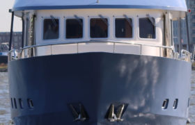
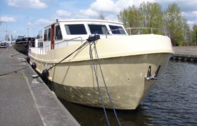
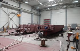
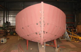
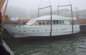
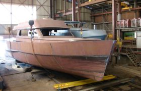
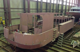
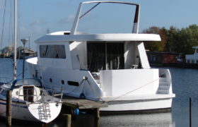
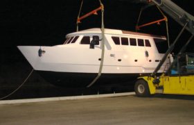
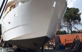
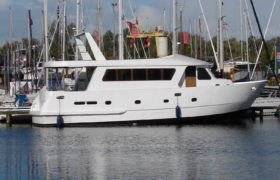
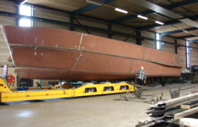
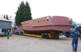
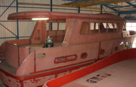
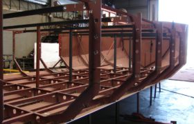
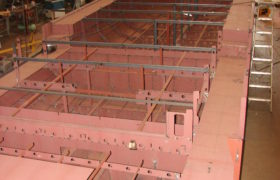
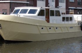
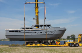
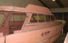
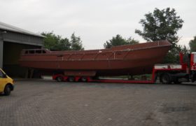
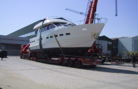
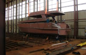
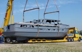
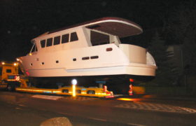
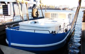
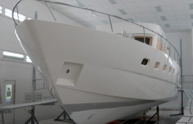
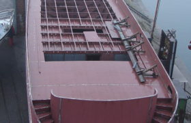
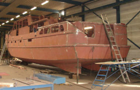
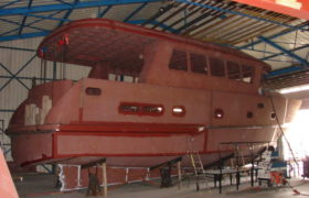
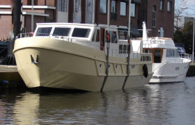
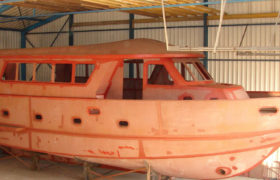
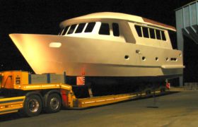
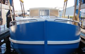
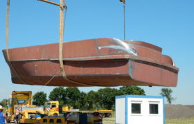
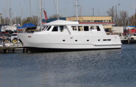
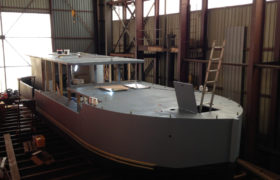
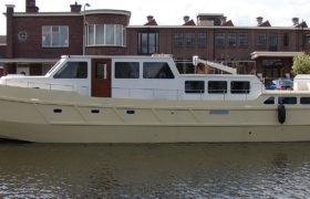
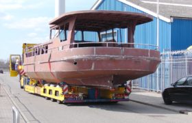
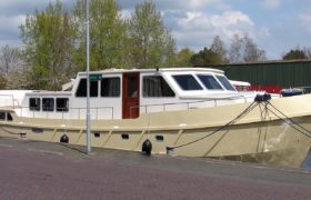
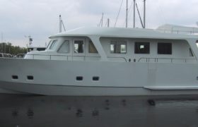
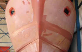
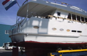
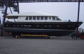
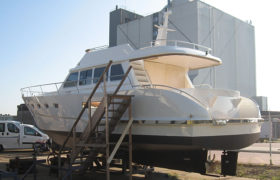
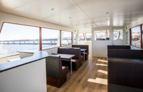
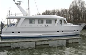
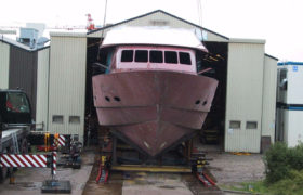
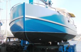
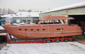
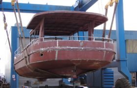
Decho has the design rights of the complete portfolio of the well know Dutch yacht and workboat design office Bonito Boats (owner now retired) and access to over 400 design and engineering project database hull and deck designs (6 to 23 meters) that have been completed for the following (and other) pleasure and commercial craft brands all over the world: Almarine | Riverfun | Seascape | Orca | Beaver Catamarans & workboats | Bonito | Passenger 57 and 73 of which you see a selection of photos: